9. Traversing Wide Area Networks
Many systems today already rely on Connext DDS to distribute their information across a Local Area Network (LAN). However, more and more of these systems are being integrated in Wide Area Networks (WANs). With Routing Service, you can scale Connext DDS real-time publish/subscribe data-distribution beyond the current local networks and make it available throughout a WAN.
Out of the box, Routing Service only uses UDPv4 and Shared Memory transports to communicate with other Routing Services and Connext DDS applications. This configuration is appropriate for systems running within a single LAN. However, using UDPv4 introduces several problems when trying to communicate with Connext DDS applications running in different LANs:
- UDPv4 traffic is usually filtered out by the LAN firewalls for security reasons.
- Forwarded ports are usually TCP ports.
- Each LAN may run in its own private IP address space and use NAT (Network Address Translation) to communicate with other networks.
To overcome these issues, Routing Service is distributed with a TCP transport that is NAT friendly. The transport can be configured via XML using the PropertyQosPolicy of the Routing Services participants.

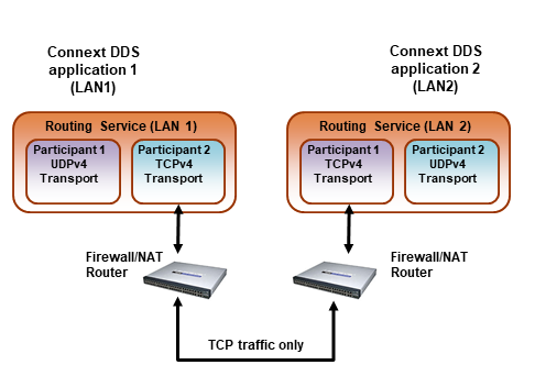
Figure 9.1 WAN Communication Using TCP Transport
Figure 9.1 shows a typical scenario where two Routing Services are used to bridge two Connext DDS applications running in two different LANs.
9.1. TCP Configuration elements
The TCP transport distributed with Routing Service can be used to address multiple communication scenarios that range from simple communication within a single LAN to complex communication scenarios across LANs where NATs and firewalls may be involved.
9.1.1. TCP Transport Initial Peers
With the TCP transport, the addresses of the initial peers (NDDS_DISCOVERY_PEERS) that will be contacted during the discovery process have the following format:
For WAN communication: tcpv4_wan://<IP address or hostname>:<port>
For LAN communication: tcpv4_lan://<IP address or hostname>:<port>
For WAN+TLS communication: tlsv4_wan://<IP address or hostname>:port
For LAN+TLS communication: tlsv4_lan://<IP address or hostname>:port
9.1.1.1. Example: Setting discovery peers for TCP wan/lan
setenv NDDS_DISCOVERY_PEERS tcpv4_wan://10.10.1.165:7400,tcpv4_wan://10.10.1.111:7400,tcpv4_lan://192.168.1.1:7500
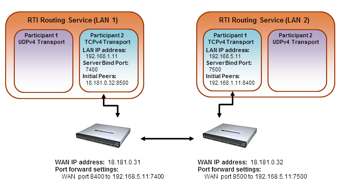
When the TCP transport is configured for LAN communication (with the parent.classid property), the IP address is the LAN address of the peer and the port is the server port used by the transport (the server_bind_port property).
When the TCP transport is configured for WAN communication (with the parent.classid property), the IP address is the WAN or public address of the peer and the port is the public port that is used to forward traffic to the server port in the TCP transport.
When TLS is enabled, the transport settings are similar to WAN and LAN over TCP. See Figure 9.2.

Figure 9.2 Initial Peers in WAN Communication
9.1.2. TCP Transport Property
You can configure the TCP transport in Routing Service in the same manner as a Connext DDS application. Transports are configured at the DomainParticipant level by means of the PropertyQosPolicy. For details, see transport plugins in RTI Connext DDS Users Manual. For a list of available transport properties for TCP, see RTI TCP Transport configuration.
9.2. Support for External Hardware Load Balancers in TCP Transport Plugin
For two Connext DDS applications to communicate, the TCP Transport Plugin needs to establish 4-6 connections between the two communicating applications. The plugin uses these connections to exchange DDS data (discovery or user data) and TCP Transport Plugin control messages.
With the default configuration, the TCP Transport Plugin does not support external load balancers. This is because external load balancers do not forward the traffic to a unique TCP Transport Plugin server, but they divide the connections among multiple servers. Because of this behavior, when an application running a TCP Transport Plugin client tries to establish all the connections to an application running a TCP Transport Plugin server, the server may not receive all the required connections.
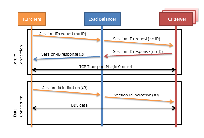
In order to support external load balancers, the TCP Transport Plugin provides a session-ID negotiation feature. When session-ID negotiation is enabled (by setting the negotiate_session_id property to true), the TCP Transport Plugin will perform the negotiation depicted in Figure 9.3.

Figure 9.3 Session-ID Negotiation
During the session-ID negotiation, the TCP Transport Plugin exchanges three types of messages:
- Session-ID Request: This message is sent from the client to the server. The server must respond with a session-ID response.
- Session-ID Response: This message is sent from the server to the client as a response to a session-ID request. The client will store the session ID contained in this message.
- Session-ID Indication: This message is sent from the client to the server; it does not require a response from the server.
The negotiation consists of the following steps:
- The TCP client sends a session-ID request with the session ID set to zero.
- The TCP server sends back a session-ID response with the session ID set to zero.
- The external load balancer modifies the session-ID response, setting the session ID with a value that is meaningful to the load balancer and identifies the session.
- The TCP client receives the session-ID response and stores the received session ID.
- For each new connection, the TCP client sends a session-ID indication containing the stored session ID. This will allow the load balancer to redirect to the same server all the connections with the same session ID.
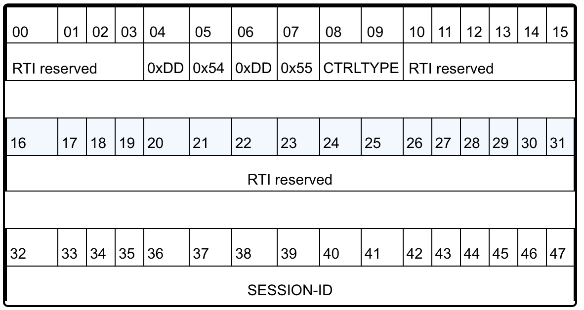
Figure 9.4 depicts the TCP payload of a session-ID message. The payload consists of 48 bytes. In particular, your load balancer needs to read/modify the following two fields:
- CTRLTYPE: This field allows a load balancer to identify session-ID messages. Its value (two bytes) varies according to the session-ID message type: 0x0c05 for a request, 0x0d05 for a response, or 0x0c15 for an indication.
- SESSION-ID: This field consists of 16 bytes that the load balancer can freely modify according to its requirements.

Figure 9.4 TCP Payload for Session-ID Message
To ensure all the TCP connections within the same session are directed to the same server, you must configure your load balancer to perform the two following actions:
- Modify the SESSION-ID field in the session-id response with a value that identifies the session within the load balancer.
- Make the load-balancing decision according to the value of the SESSION-ID field in the session-ID indication.