2. Routing Data: Connecting and Scaling Systems
This chapter is devoted to present the most elemental function of Routing Service: routing data across multiple DDS domains. Routing data refers to the process of propagating the Topic user data from domain to another, allowing systems to interconnect and scale.
Figure 2.1 shows the most basic view of the Routing Service model. You can think of it as a black box composed of multiple Input DataReaders and Output DataWriters, each associated with a specific Topic. Data flows from the input DataReaders to the output DataWriters. The input DataReaders receive data from the publication side, whereas the output DataWriters send data to the subscription side.
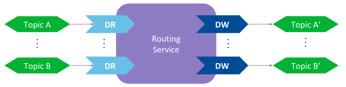
Figure 2.1 Basic model of Routing Service
The Routing Service engine takes the data from an input DataReader and passes it along to a specific output DataWriter, as if there was a link connecting input and output. This activity is known as the forwarding process. Routing Service allows configuring this forwarding process.
The following sections will guide you through all the Routing Service entities involved in the forwarding process and how they are configured.
Note
All the following sections assume you are already familiar with basic DDS concepts. Additionally you should be familiar with the RTI Shapes Demo tool. Refer to Tutorials if you need more information.
2.1. Routing a Topic between two different domains
The most basic use case of Routing Service is about forwarding the data for a specific Topic from one domain to another. This process is known as routing a Topic. Figure 2.2 illustrates this concept.
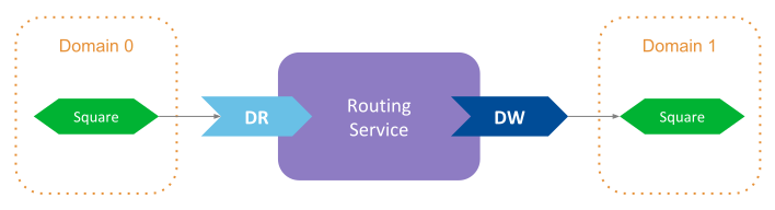
Figure 2.2 Basic Topic routing among domains for a Topic with name Squares
The samples for the Topic named Square in domain 0 are forwarded to
the same Topic but in domain 1. You will first run
Example: Routing a single specific Topic in your machine to see the
functionality in action. Then we will break down all the parts related to Routing Service.
Let’s review step-by-step each element that appears in the Routing Service XML configuration, understanding its purpose and what each of its entities is modeling.
2.1.1. Define the service configuration element
The first step is to define the top-level element for the Routing Service configuration:
<routing_service name="SquareRouter">
    ...
</routing_service>
This element defines a configuration profile for Routing Service. It must appear within
the tag <dds>–the root tag for all the elements related to Connext DDS–. The
configuration shall contain a name attribute that uniquely identifies the
service, and determines the service configuration name. You can define
multiple service configurations in one XML file, and select one to instantiate
a Routing Service by providing the configurations name with the -cfgName option (or
ServiceProperty::cfg_name member when using the Service API).
As we’ll see further below, the name attribute is an important concept since
it establishes the configuration name of a Routing Service entity. This name can be used
from other elements in the configuration to refer to a specific entity.
See also
- Usage
How to run Routing Service using the shipped executable or embeddeding it into your application with the Service API.
- Routing Service Tag
Reference for the XML configuration of the service element.
2.1.2. Specify which domains to join
Within the top-level Routing Service configuration we need to specify which domains Routing Service will be joining. The specification of the domains occurs within the DomainRoute, which represents a mapping between multiple DDS domains through a collection of DomainParticipants.
In our example, we are joining domains 0 and 1 and we relay on the default participant QoS settings, so the XML looks as follows:
<domain_route name="DomainRoute">

    <participant name="domain0">
        <domain_id>0</domain_id>
    </participant>

    <participant name="domain1">
         <domain_id>1</domain_id>
    </participant>

    ...
</domain_route>
You can specify as many DomainParticipants as needed. An important aspect to pay attention is the configuration name assigned to each participant. This name is what uniquely identifies a domain and is referenced later by Inputs and Outputs to indicate the DomainParticipant from which the DataReader and DataWriter are created, respectively.
Note
The value specified with <domain_id>> in the XML participant configuration
can be offset with the -domainIdBase command-line option. The participant
will be created with domain ID = <domain_id> + -domainIdBase.
In addition, the name attribute of the participant configuration is used
to form the name assigned to the actual DomainParticipant by setting the
EntityName QoS.
See also
- Table 8.8 in Domain Route
How Routing Service constructs the name assigned to the DomainParticipant.
Figure 2.3 shows the DomainRoute resource model, denoting the association with the service and participant entities.
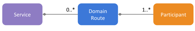
Figure 2.3 DomainRoute resource model
2.1.3. Define a processing context
One of the main aspects that contributes to the high performance of Routing Service is the ability to parallelize the processing of the data streams. You can create threading contexts to execute of all the activities related to the processing of the data streams. A threading context involves one or more threads–a thread pool–, and is specified by the Session entity.
In our example we define a single Session to take care of processing the data for the single Topic that is forwarded:
<session name="Session">

    ...
</session>
The Session must appear inside the DomainRoute and you can specify as many Sessions as you want. In our configuration we rely on the default values, which define a single-threaded context. You could specify a thread pool if, for example, you wanted to parallelize the forwarding of multiple Topics.
Figure 2.4 shows the Session resource model.
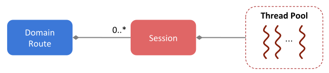
Figure 2.4 Session resource model
See also
- Session configuration in Session
Reference for the XML configuration of the Session element.
2.1.4. Define the data flow
The last step consists of defining the flow of data streams. For the Topic routing use case, we need to indicate that the data from a Topic in the publication side shall be routed to the same topic in the subscription side. The TopicRoute is the entity that allows you to define these data flows for the forwarded data.
A TopicRoute is a data processing unit composed of the DDS Inputs and Outputs that receive and send the data, respectively. Hence a TopicRoute effectively represents the establishment of a route that data streams follow. Data from the publication side is forwarded to the subscription side.
In our example we just define a TopicRoute with a single Input–containing a DataReader– and a single Output–containing DataWriter–.
<topic_route name="RouteSquare">
    <input participant="domain0">
         <topic_name>Square</topic_name>
         <registered_type_name>ShapeType</registered_type_name>
    </input>
    <output participant="domain1">
         <topic_name>Square</topic_name>
         <registered_type_name>ShapeType</registered_type_name>
    </output>
</topic_route>
Notice how the Input and Output are attached to a concrete DomainParticipant using the
the participant attribute. The value of this attribute is the name of one
the participant configurations defined in the parent DomainRoute. This is how
you indicate to which domain the Input and Output are connected to–or from
which DomainParticipant the DataReader and DataWriter are created, respectively–.
In our example, the Input is attached to the participant configuration with name
domain0 for domain 0, whereas the Output is attached to domain1 for domain 1.
Additionally, for each Input and Output we need to specify at least two elements:
Name of their associated Topic. This indicates the name of the topic for which the DataReader and DataWriter are created. In this example, both entities are created from the
Squaretopic.Registered name of the type associated with the Topic. This is the name used to identify the type of the user-data samples that are read and written by the input DataReader and output DataWriter. Routing Service needs to obtain the information prior to create the DataReader and DataWriter. There are two provide the type information:
Manually by defining the type in XML
Through discovery from any of the DomainParticipant within the parent DomainRoute. This is the mechanism our example relies to get the type and in this case the type is identified by the registered name
ShapeType(you can find the the definition of this type in[NDDSHOME]/resource/idl/ShapeType.idl)
You can learn more about type registration and how to configure it in Specifying Types.
For this case of routing a Topic, both the input and output topic its associated type are the same. This is often the situation when you want to simply route data across domains for system integration and scalability. Nevertheless, Routing Service is flexible to allow using different topics and types. In that case you will need to plug custom code to perform the routing. Controlling Data: Processing Data Streams addresses this use case.
Figure 2.5 shows the TopicRoute resource model.
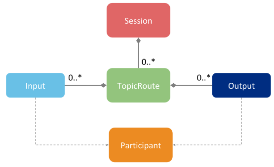
Figure 2.5 TopicRoute resource model
See also
- TopicRoute configuration in Route
Reference for the XML configuration of the TopicRoute element.
2.2. Routing a group of Topics
In section Routing a Topic between two different domains we learned how to route a specific Topic. We showed how to create a dedicated TopicRoute to forward the data for a concrete Topic. You can replicate this process for each Topic you want to route.
However, this process may become repetitive and in some cases avoidable. When such is the case, you can use the AutoTopicRoute to automate the routing for a group of Topics. An AutoTopicRoute allows you to specify a set of potential TopicRoutes that Routing Service will create on-demand upon dynamic discovery of the Topic to be routed.
Figure 2.6 shows the concept of the AutoTopicRoute. An AutoTopicRoute specifies a regular expression that is applied upon the discovery of any new Topic. The AutoTopicRoute creates a new TopicRoute for each newly discovered Topic whose name matches with the AutoTopicRoute’s expression.
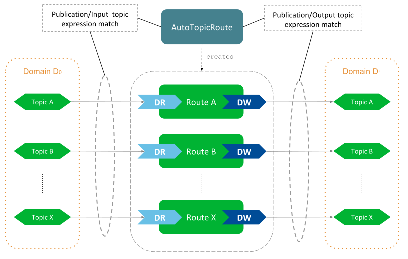
Figure 2.6 AutoTopicRoute concept
An AutoTopicRoute allows defining a set of potential TopicRoutes that have a single Input and a single Output, both tied to their corresponding domain. A regular expression can be specified separately for publication and subscription Topics. Hence, when the AutoTopicRoute matches either with a publication or subscription Topic, it will create a TopicRoute to route the matched Topic.
Let’s first run Example: Routing All Data from One Domain to Another to see this functionality. This example shows how to configure a Routing Service to route all the Topics from domain 0 to domain 1 using an AutoTopicRoute. To accomplish that, we have defined the AutoTopicRoute as follows:
<auto_topic_route name="RouteAll">
    <publish_with_original_info>true</publish_with_original_info>
    <input participant="domain1">
        <allow_topic_name_filter>*</allow_topic_name_filter>
        <allow_registered_type_name_filter>*</allow_registered_type_name_filter>
        <!--
             Exclude RTI monitoring, administration and logging
             topics. They all start with 'rti/'
         -->
        <deny_topic_name_filter>rti/*</deny_topic_name_filter>
    </input>
    <output participant="domain2">
        <allow_topic_name_filter>*</allow_topic_name_filter>
        <allow_registered_type_name_filter>*</allow_registered_type_name_filter>
        <!--
             Exclude RTI monitoring, administration and logging
             topics. They all start with 'rti/'
        -->
        <deny_topic_name_filter>rti/*</deny_topic_name_filter>
    </output>
</auto_topic_route>
The configuration of the AutoTopicRoute is such that matches the name and registered type
name of every Topic on either domain1 or domain2, except the Topics
whose name starts with rti/.
An AutoTopicRoute allows you to specify two sets of regular expressions for both the input and output of the potential TopicRoutes:
allow_topic_name_filterandallow_registered_type_name_filterspecify the set of Topic names and types that are accepted for the dynamic creation of TopicRoutes. If both expressions evaluate as true, a new TopicRoute will be created, unless one of the deny filter evaluates as true.deny_topic_name_filteranddeny_registered_type_name_filterspecify the set of Topic names and types for which the creation of TopicRoutes is denied. If any of the expressions evaluate as true, the creation of the TopicRoute will be rejected. These expressions are evaluated after the allow filters, and only if these evaluated as true.
The configuration for the input and output of the AutoTopicRoute can contain a DataReader and DataWriter QoS respectively. You can leverage the concept of QoS topic filters to use a different QoS profile based on the name of the matched Topic (See Applying topic filters to DDS Inputs and Outputs).
You can also observe from the example that the AutoTopicRoute is defined under a Session. This means that all the created TopicRoutes will run under that context. Figure 2.7 shows the AutoTopicRoute resource model.
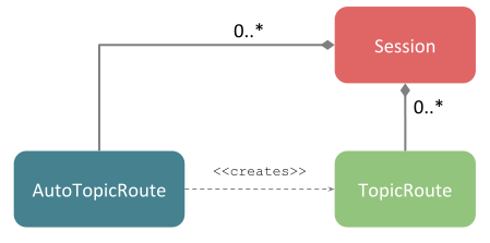
Figure 2.7 AutoTopicRoute resource model
See also
- TopicRoute configuration in Auto Route
Reference for the XML configuration of the AutoTopicRoute element.
2.3. Using custom QoS Profiles
In the previous sections, we showed scenarios in which all the DDS entities of Routing Service are created with default QoS. That is, all the QoS policies are set with the initial default values as specified in the Connext DDS documentation (see QoS Reference Guide).
For the majority of the cases though, you may want to specify your custom QoS values for the DDS entities of Routing Service. You can easily do that in XML by defining your QoS Profiles and inherit from them when specifying the configuration of QoS for each DDS entity.
Let’s take a look to each step individually.
2.3.1. Defining a QoS Library
You can define XML QoS profiles for Routing Service the same way you can do it for a regular
Connext DDS application. You can define QoS libraries containing profiles directly
under the <dds> root element. For example:
<dds>
    <qos_library name="MyQosLibrary">
         <qos_profile name="MyQoSProfile">
             <domain_participant_qos>
                 ...
             </domain_participant_qos>

             <subscriber_qos>
                 ...
             </subscriber_qos>

             <publisher_qos>
                 ...
             </publisher_qos>

             <datareader_qos>
                 ...
             </datareader_qos>

             <datawriter_qos>
                 ...
             </datawriter_qos>
        </qos_profile>
    </qos_library>
</dds>
As we will see shortly in the next step, within the Routing Service configuration you can reference these profiles in order to configure the corresponding underlying DDS entities.
You can define as many QoS libraries as you want, each with multiple profiles. Additionally, the definition of QoS libraries can appear either in the same file that contains the Routing Service configuration or in a separate one. For information on how to configure QoS in XML, see Configuring QoS with XML in the RTI Connext User’s Manual.
See also
- Loading XML configurations in Configuring RTI Services
How lo load XML configurations in Routing Service.
2.3.2. Specifying QoS for DDS entities
You can configure the QoS for each DDS entity that Routing Service creates. To accomplish this, each Routing Service entity that creates an underlying DDS entity provides a corresponding tag to specify its QoS.
For example, to configure the QoS for the DomainParticipants of a DomainRoute, you can specify
a <participant_qos> tag as follows:
<domain_route name="DomainRoute">

    <participant name="domain0">
        <participant_qos base_name="MyQosLibrary::MyQosProfile">
            <!-- You can override inline any value -->
            ...
        </participant_qos>
        ...
    </participant>

    ...
The QoS tag can have a base_name attribute to inherit from any available QoS
profile, including builtin QoS profiles. Additionally,
inline values for QoS policies can be specified in order to override default values
or set by the base profile.
Table 2.1 shows the a list of Routing Service entities and the DDS entities they create, along with the tags that configure them.
Routing Service Entity |
DDS Entity |
QoS tag |
|---|---|---|
DomainRoute |
DomainParticipant |
Example:
|
Session |
Publisher |
Example:
|
Subscriber |
Example:
|
|
TopicRoute’s Input or AutoTopicRoute’s Input |
DataReader |
Example:
|
TopicRoute’s Output or AutoTopicRoute’s Output |
DataWriter |
Example:
|
2.3.3. Applying topic filters to DDS Inputs and Outputs
You can leverage the concept of topic filters to select a QoS for a DDS Input’s DataReader and Output’s DataWriter. You simply need to define a QoS profile containing top-level QoS with a topic filter each, and then inherit from this profile when you specify the QoS for the input DataReader and output DataWriter. Routing Service will select the appropriate QoS when it creates the DataReader and DataWriter based on the name of their associated Topic.
For example, consider a system where there are three types of Topic categories: user data, monitoring, and administration. Each category has different QoS requirements. You could define a QoS Profile that contains three different DataReader QoS configurations, one for each category:
<qos_library name="MyQosLibrary">
     <qos_profile name="MyQoSProfileWithFilters">

         <datareader_qos topic_filter="UserData_*"> ...  </datareader_qos>

         <datareader_qos topic_filter="Monitoring_*"> ...  </datareader_qos>

         <datareader_qos topic_filter="Admin_*"> ...  </datareader_qos>

         <!-- Same idea for the datawriter_qos -->
         ...
    </qos_profile>
</qos_library>
Then you can define an AutoTopicRoute to route all the Topics in the system by simply indicating that the input DataReader shall be created using with the QoS obtained from our profile:
<auto_topic_route name="RouteAll">
    <input participant="domain0">
         <datareader_qos base_name="MyQosLibrary::MyQoSProfileWithFilters">
    </input>
    <output participant="domain1">
         <datawriter_qos base_name="MyQosLibrary::MyQoSProfileWithFilters">
    </output>
</auto_topic_route>
When the AutoTopicRoute creates a TopicRoute for a matching publication or subscription Topic, the QoS for the TopicRoute’s input and output is resolved by matching the topic filter against the Topic name.
The topic filter is applied at the time the AutoTopicRoute matches with a publication or subscription Topic, so the right topic name can be used to match against the topic filter. The selected QoS will be used to create the input DataReader and output DataWriter of the generated TopicRoute.
2.4. Traversing Wide Area Networks
In the previous sections we learned to how to route Topics between domains, understanding the steps required to join the domains, and defining the TopicRoutes or AutoTopicRoutes to route the data. In this section, we will focus on routing data between domains separated geographically.
Many systems today have the need to communicate over Wide Area Networks (WAN). This may be the case to connect systems separated geographically. More importantly, it may be the case to provide system connectivity to and within the cloud. Access to data centers is often common when there’s a requirement for data analytics.
You can use Routing Service to provide WAN connectivity between sub-systems composed of multiple applications communicating over a Local Area Network (LAN). This architecture allows you to scale the global system efficiently creating multiple databus layers dispersed over the WAN. Figure 2.8 shows this use case.
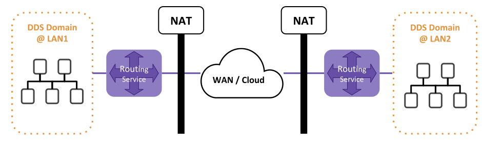
Figure 2.8 WAN traversal with Routing Service.
Routing Service can act as an entiry/exit gateway to provide connectivity to a WAN or cloud-based data center. The applications running in a LAN only need to know how to reach their gateway Routing Service. Only the gateway services need to know to contact each other, and they shall be publicly accessible through the WAN. This model simplifies the network configuration under presence of NATs/Firewalls, since they just need to be configured to forward the traffic only between the gateway Routing Service.
You can benefit from this architecture by configuring Routing Service to use a WAN-enabled Transport to provide communication outside of the private LAN or shared memory network. Figure 2.9 illustrates this setup.
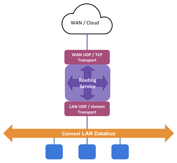
Figure 2.9 Routing Service as WAN/Cloud gateway
We will demonstrate how this is possible through the Example: WAN Connectivity using the TCP transport. This example will help you understand how Routing Service can route Topics between two geographically separated DDS domains comprised of a set of Connext DDS applications connected in a LAN. The example scenario is shown in Figure 2.10.
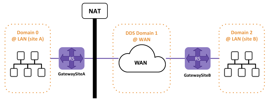
Figure 2.10 Example using the TCP transport to traverse WAN
First run the example to see the communication flowing between the RoutingServices. You can run all the steps in the same machine for a quicker setup. Let’s go through the steps to configure the gateway Routing Service.
Note
For better understanding of this section, we recommend you get familiar with the RTI TCP Transport.
2.4.1. Define a QoS profile that configures the RTI TCP transport
The configuration of the transport is done through the Property QoS for the DomainParticipant. It requires specifying a set of properties to load the transport library (if it’s an external transport plugin) and specific values to configure its behavior. To avoid repeating the same configuration for each participant in Routing Service, we define a base profile with all the common properties:
<qos_library name="QosLib">
    <qos_profile name="TcpWanProfile">
        <!--
            We define here the common properties to configure the TCP transport,
            which includes mostly the loading of the transport implementation library.
            Specific values for public address and port are set appropriate on each
            Routing Service.
        -->
        <domain_participant_qos>
            <transport_builtin>
                <mask>MASK_NONE</mask>
            </transport_builtin>
            <property>
                <value>
                    <element>
                        <name>dds.transport.load_plugins</name>
                        <value>dds.transport.TCPv4.tcp1</value>
                    </element>
                    <element>
                        <name>dds.transport.TCPv4.tcp1.library</name>
                        <value>nddstransporttcp</value>
                    </element>
                    <element>
                        <name>dds.transport.TCPv4.tcp1.create_function</name>
                        <value>NDDS_Transport_TCPv4_create</value>
                    </element>
                    <element>
                        <name>dds.transport.TCPv4.tcp1.parent.classid</name>
                        <value>NDDS_TRANSPORT_CLASSID_TCPV4_WAN</value>
                    </element>
                    <element>
                        <name>dds.transport.TCPv4.tcp1.public_address</name>
                        <value>$(PUBLIC_ADDRESS)</value>
                    </element>
                    <element>
                        <name>dds.transport.TCPv4.tcp1.server_bind_port</name>
                        <value>$(BIND_PORT)</value>
                    </element>
                    <element>
                        <name>dds.transport.TCPv4.tcp1.disable_nagle</name>
                        <value>1</value>
                    </element>
                </value>
            </property>
            <discovery>
                <initial_peers>
                    <element>$(REMOTE_RS_PEER)</element>
                </initial_peers>
            </discovery>
        </domain_participant_qos>
    </qos_profile>
</qos_library>
In addition to the transport configuration, the profile also sets the value for the initial peers required for the DomainParticipant of the Routing Service to reach the peer remote gateway.
For the definition of this profile, we’re leveraging the XML configuration variables to reduce even more code duplication. Namely, we define the following variables that are set accordingly when running each Routing Service:
PUBLIC_ADDRESS: the public IP address and public port where the Routing Service is reachable.BIND_PORT: the host port that the TCP connection of the Routing Service is bound to. This value is important to create a port forwarding rule between public port and host port in the NAT configuration.REMOTE_RS_PEER: shall contain the discovery peer of the remote Routing Service to communicate over the WAN. In this example, the remote peer is the public address and public port of the Routing Service gateway for the remote site. This value is used as the initial peers of the DomainParticipant that provides WAN connectivity. See discovery peer configuration for details on setting discovery peers.
See also
- Transport Plugins
Documentation for the Connext Transport Plugin conncept.
- RTI TCP Transport properties
Available configuration properties for the RTI TCP Transport.
2.4.2. Specify the domains to join and which transport to use
This is the key step that makes possible to forward data from a DDS application in a LAN to the WAN. The main idea is to define two different DomainParticipants to provide access to the different networks. Figure 2.11 shows the entity model of the DomainRoute with its two DomainParticipants, each using a different underlying transport to communicate with different networks.
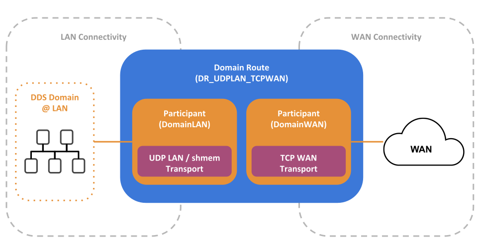
Figure 2.11 Configuration of the DomainRoute to forward data over the WAN
The DomainLAN DomainParticipant is configured to join domain 0 and use the default UDPv4 LAN
and shared memory transports to communicate with the applications on the site A LAN.
Alternatively, The DomainWAN DomainParticipant is configured to join domain 1 and use the
RTI TCP Transport to communicate over the WAN. DomainWAN is the gateway DomainParticipant
that communicates with the remote Routing Service gateway at a different location.
The definition of these participants appear in a DomainRoute as follows:
<domain_route name="DR_UDPLAN_TCPWAN">
    <!--
        With default participant QoS, which uses UDP LAN and Shared memory
        as trasnports
    -->
    <participant name="DomainLAN">
        <domain_id>0</domain_id>
    </participant>

    <participant name="DomainWAN">
        <domain_id>1</domain_id>
        <!--
            With participant QoS configured to use the TCP transport. Requires
            setting the variableS PUBLIC_ADDRESS AND BIND_PORT to the actual
            values used in to route the traffic to this RS.
        -->
        <participant_qos base_name="QosLib::TcpWanProfile"/>
    </participant>
</domain_route>
You can observe how the DomainWAN participant is configured with a QoS that
inherits from the QosLib::TcpWanProfile, which configures the RTI TCP transport,
in addition to other discovery settings. The QoS for this participant provides two
additional transport properties to configure the TCP server public address and
bind port.
2.4.3. Specify the Topics to be routed
In this example we want to route all the topics between the LAN domains, and we want the communication to be bidirectional. We’ll do this by defining two AutoTopicRoutes to forward any Topic for a different communication direction each. We’ll place both under a single Session configured with default settings:
<session name="Session">
    <auto_topic_route name="FromLANtoWAN">
        <input participant="DomainLAN">
            <deny_topic_name_filter>rti/*</deny_topic_name_filter>
        </input>
        <output participant="DomainWAN">
            <deny_topic_name_filter>rti/*</deny_topic_name_filter>
        </output>
    </auto_topic_route>

    <auto_topic_route name="FromWANtoLAN">
        <input participant="DomainWAN">
            <deny_topic_name_filter>rti/*</deny_topic_name_filter>
        </input>
        <output participant="DomainLAN">
            <deny_topic_name_filter>rti/*</deny_topic_name_filter>
        </output>
    </auto_topic_route>
</session>
AutoTopicRoute FromLANtoWAN is configured to forward any Topic coming from the LAN
domain to the WAN domain. FromWANtoLAN AutoTopicRoute is configured to forward any
Topic coming from the WAN domain–which connects to the remote LAN Domain–to the
local LAN domain.
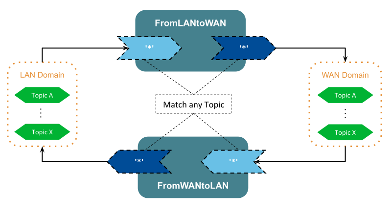
Figure 2.12 Definition of AutoTopicRoute to forward topics bidirectionally
Figure 2.12 illustrates the definition of the AutoTopicRoutes to forward all topics between the LAN and WAN domains. Each AutoTopicRoute is configured with both input and output filters to match any Topic. The difference between the AutoTopicRoutes is simply the domain assigned to the Input and Output–the DomainParticipant from which the input DataReader and output DataWriter will be created–.
2.5. Key Terms
- Forwarding Process
The action of routing data from input to output.
- Entity Configuration Name
Name assigned to uniquely identify an entity. Specified by the attribute
name.- Publication Side
Side of the communication from where Routing Service inputs receive data.
- Subscription Side
Side of the communication t0 where Routing Service outputs write data.
- Resource model
A model to represent Routing Service entities viewed as resources and their relationships.
- DomainRoute
A collection of DomainParticipants.
- Session
The threading context where the forwarding process takes place.
- TopicRoute
Processing unit for data streams. Composed of multiple Inputs and Outputs.
- AutoTopicRoute
Factory of TopicRoutes based on topic name regular expression matching.
- Input
Entity that reads data from a specific domain. For DDS domains, it contains an underlying DataReader.
- Output
Entity that that writes to a specific domain.For DDS domains, it contains an underlying DataWriter.
- Transport
Internal component of a DomainParticipant that provides connectivity to a concrete network technology.
- Discovery Peer
A DDS address that identifies a remote application.