RTI Use Case for Vehicle Tracking Systems
Use Case for Vehicle Tracking: High Throughput and Low Latency Data
This use case applies if you need to distribute vehicle location or radar track data to:
- Air traffic control systems
- Situational awareness systems
- Warning systems
- Self-defense systems
- Area defense systems
- Logging systems
- Collision avoidance systems
- Emergency vehicle tracking systems
- Rail tracking systems
- Bus and transport applications
RTI Connext DDS is peer-to-peer middleware that fits the requirements of high-performance vehicle monitoring and radar tracking systems. In this document, we'll look at an air traffic control example that illustrates how RTI Connext DDS provides a solution for sending high-performance object tracking data. We'll also go step-by-step through example air traffic control applications that show how to send rapid sensor data into the network, how to tune for different application requirements, how to trade off throughput and latency in your network, and how to access data.
What This Example Does:
This example shows three applications. You can run them on the same machine or separate machines in the same network. This example shows radar tracks, but the concepts and the quality of service (QoS) tuning is also applicable for other vehicle-tracking use cases. There are minor differences in the data model, described in this section.
The three applications are:
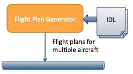
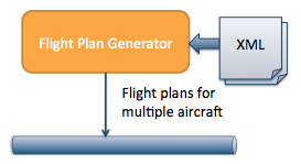
1. Flight-plan generator (FlightPlanGenerator):
| 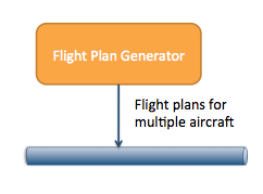 |
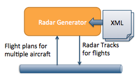
2. Radar generator (RadarGenerator):
| 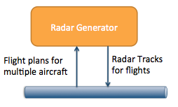 |
3. Air traffic control GUI (TrackGui):
| 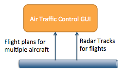 |
Download the Example
<TODO>
The location you unzip this example to will be called EXAMPLE_HOME.
Download RTI Connext DDS
If you do not already have RTI Connext DDS installed, download and install it now. You can use a 30-day trial license to try out the product. Your download will include the libraries that are required to run the example, and tools you can use to visualize and debug your distributed system.
Run the Example
Windows
Navigate to the EXAMPLE_HOME\scripts directory.
In this directory, there are three separate batch files to start the applications. These are called
- FlightPlanGenerator.bat
- RadarGenerator.bat
- TrackGui.bat
You can run these batch files on the same machine, or you can copy this example and run on multiple machines. If you run them on the same machine, they will communicate over the shared memory transport. If you run them on multiple machines, they will communicate over UDP.
You should see track data and flight-plan information in the air traffic control GUI.
If you have access to multiple machines on the same network, start running these applications on separate machines. Note: If you do not have multicast on your network, see the section My Network Doesn't Support Multicast for details on how to change the configuration to run without multicast.
Running the Example on Windows
Linux
Navigate to the EXAMPLE_HOME/scripts directory.
In this directory, there are three separate script files to start the applications. These are called
- FlightPlanGenerator.sh
- RadarGenerator.sh
- TrackGui.sh
You can run these scripts on the same machine, or you can copy this example and run on multiple machines. If you run them on the same machine, they will communicate over the shared memory transport. If you run them on multiple machines, they will communicate over UDP.
Notice how you can see track data and flight-plan information in the air traffic control GUI. If you are running all the applications on a single machine, this data is being sent over shared memory.
If you have access to multiple machines on the same network, start running these applications on separate machines. Note: If you do not have multicast on your network, see the section My Network Doesn't Support Multicast for details on how to change the configuration to run without multicast.
Running the Example on Linux
Configure Throughput and Latency for Your Requirements
RTI Connext DDS allows you to specify QoS configuration in an XML format. This allows you to separate your application logic from yournetwork capabilities and rapidly reconfigure your application for new deployment scenarios.
This example shows you how to configure your application to maximize throughput at the expense of latency, or minimize latency at the expense of throughput.
Individual vehicle or radar tracking applications within a distributed system will have different requirements for data latency or throughput. A collision-avoidance system or a self-defense system may have strict requirements for low latency. A recording or logging system may need to record a high throughput of vehicle position or radar track data, but may not need to receive it with the low latency of your other applications.
Run the Example with Increased Throughput and Increased Latency
By default, the radar generator application runs with the lowest possible latency. To run it with increased throughput at the expense of latency, use the following parameter:
scripts/RadarGenerator --high-throughput
You can also increase the maximum number of tracks it can send at once using the following parameter:
scripts/RadarGenerator --max-tracks <number of tracks>
Lastly, you can increase the send rate of tracks using the following parameter:
scripts/RadarGenerator --send-rate <rate to send in milliseconds>
A Walk Through the Example Code
Code Overview
- The source code is divided into:
- Linux makefiles in make/
- Windows solution files in win32/
- Source in src/
- RTI Connext DDS interface data type descriptions in Idl/. This describes the data types sent over the network.
- RTI Connext DDS QoS configurations in Config/
- RTI Connext DDS infrastructure code that is used by all applications in CommonInfrastructure/. This is the code that all applications call to start using RTI Connext DDS to send data.
- Application-specific RTI Connext DDS publishing and subscribing code in FooInterface.h and FooInterface.cxx
Hands On: How to build this code
On all platforms, the first thing you must do is set an environment variable called NDDSHOME. This environment variable must point to the ndds.5.x.x directory inside your RTI Connext DDS installation. For more information on how to set an environment variable, please see the RTI Core Libraries and Utilities Getting Started Guide.
Windows
On Windows, start by opening up the
win32\AirTrafficExample-<compilerver>.sln file.
This code is made up of a combination of libraries, source, and IDL files that represent the interface to the application. The Visual Studio solution files are set up to automatically generate necessary code and link against the required libraries.
Building the Example on Windows
Linux
To build the applications on Linux, change directories into the ExampleCode directory, and use the command:
gmake –f make/Makefile.<platform>
The platform you choose will be the combination of your processor, OS, and compiler version. For example, i86Linux2.6gcc4.5.5
Building the Example on Linux
Configuration Details: XML Configuration for Radar Performance
Since a major component of building a radar or vehicle-tracking system is performance tuning, we'll talk about that first, before going into too much detail about the code itself. The source code loads a series of XML files that it uses to configure the delivery and resource characteristics for the data. The .xml files are in the Config directory; they specify the communication characteristics for the data, such as whether the data is reliable. XML QoS profiles can inherit from each other.
Multicast
Multicast is enabled in the multicast_base_profile.xml file.
In the example, the use of multicast is encapsulated in a QoS profile called "OneToManyMulticast." Because multicast does not hurt latency, the other QoS profiles inherit from this profile. Note that if your network does not support multicast, these are steps you must take.
     <qos_profile name="OneToManyMulticast">
       <datareader_qos>
         <multicast>
           <value>
             <element>
               <!-- Must be a valid multicast address-->
               <receive_address>239.255.5.1</receive_address>
             </element>
           </value>
         </multicast>
       </datareader_qos>
    </qos_profile>
Batching
Batching small data enables throughput at the expense of latency. The Radar's default profile "LowLatencyRadar" does not use batching. Batching is enabled in the "HighThroughputRadar" configuration.
    <batch>
        <enable>true</enable>
        <!-- If the batch hits 1024 bytes, flush to the network -->
        <max_data_bytes>1024</max_data_bytes>
        <!-- You can decide on the maximum amount of additional latency
             you are willing to sacrifice for better throughput. -->

       <max_flush_delay>
         <sec>0</sec>
         <nanosec>200000000</nanosec>
       </max_flush_delay>
    </batch>
Code Details: DDS infrastructure for all applications
Now let’s look at the code that you will write once and use in every DDS application. The code in CommonInfrastructure/DDSCommunicator.h/.cxx creates the basic objects that start DDS communications. The DDSCommunicator class encapsulates the creation and initialization of the DDS DomainParticipant object.
All applications need at least one DomainParticipant to discover other RTI Connext DDS applications and to create other DDS Entities. More information on what a DomainParticipant does is on this page. Typically, an application has only one DomainParticipant.
In the source code, you can see this in the class DDSCommunicator, in CommonInfrastructure/DDSCommunicator.cxx:
DomainParticipant* CreateParticipant(long domain,
           char *participantQosLibrary, char *participantQosProfile)
{
    _participant =
        TheParticipantFactory->create_participant_with_profile( domain,
                                    participantQosLibrary,
                                    participantQosProfile, NULL,
                                    STATUS_MASK_NONE);
...
}
The DomainParticipant's QoS is loaded from one or more XML files. The profile to load is specified by the participantQosLibrary and participantQosProfile. The full list of DomainParticipant QoS is on this page.
Hands On: Viewing the Application using Tools
To get an idea of what these applications are creating, you can use the
RTI Analyzer tool to see:
- What Topics they are sending and receiving on the network
- What the structure of the applications' data looks like
The RTI Analyzer tool must be configured to communicate in the same domain that your application is using. This video shows how to get started using RTI Analyzer and how to view your data types.
Bonus Hands On: Changing the domain in code
You can change the domain used by RadarGenerator by changing this code snippet in RadarInterface.cxx:
if (NULL == CreateParticipant(0, qosFileNames, libName, profileName))
Change the '0' to a different number between 0 and 232 and now this application is in a different domain. Run the application.
Now it will no longer discover or communicate with the other applications. Separation of domains is useful if you have subsystems in your distributed system that should not communicate. This is also useful if you have multiple developers working on the same project and you do not want their applications or tests interfering with each other.
Change the application back to domain 0 and rebuild.
RadarGenerator (C++):
This application sends and receives data over the network. The code to create the application's DDS interface is in the class RadarInterface. This class is composed of three objects:
- DDSCommunicator
- RadarWriter
- FlightPlanReader
The DDSCommunicator object creates the necessary DDS Entities that are used to create the RadarWriter and FlightPlanReader Entities.
The RadarWriter class is a wrapper around a DDS DataWriter that sends radar data. The FlightPlanReader class is a wrapper around a DDS DataReader that receives flight plan data.
Sending Data
The application publishes the track data in the PublishTrack() call. The RTI Connext DDS call that actually sends data over the network is _trackWriter->write(track, handle). This call accepts the data that will be sent over the network, and a handle to the data. In this example, we pass in a NIL handle. However, you can get increased performance in some cases by pre-registering your data and using the handle.
The application publishes a track drop message in the DeleteTrack() call. It does this by calling _trackWriter->dispose(track, handle).
Radar Data Model

Data Type
Radar is modeled in the AirTrafficControl.idl file.
Note: RTI Connext DDS uses IDL, the Interface Definition Language defined by the OMG to define language-independent data types. Moreinformation about IDL can be found in the RTI Connext DDS Users Manual.
The radar data type is:
struct Track {
  long radarId; //@key
  long trackId; //@key
  ...
};
This is modeled as very simple data, with only a few fields. The most important thing to notice is that the track ID and a radar ID are marked with the tag //@key. This indicates that these IDs make up the unique identifier of an individual track. The flight ID may or may not be available when the track is created, so it is not part of the unique ID of a track. More information about uniquely identifying elements of your data can be found in this best practice.
The data also has a latitude, longitude, and altitude. We could optionally add more fields such as bearing and speed.
Topic
The radar data can be represented as a single Topic. It is a best practice to define the Topic name inside your IDL because the Topic name is part of the interface.
const string AIR_TRACK_TOPIC = "AirTrack";
Radar Data Delivery Characteristics (QoS):
Default:
Radar data is sent rapidly, so it could potentially be sent without reliability enabled. However, it is important that the receiving application receives the last update of the radar data, so we have enabled reliability in this example, combined with a history of 1. This means that the application will reliably deliver whatever is in its queue and ensures that the last piece of data that is sent (the drop message) is guaranteed to be delivered.
Beyond this, the radar data is tuned for low-latency high-throughput data.
High Throughput:
As described above, in this example we can increase throughput at the expense of latency by enabling batching.
Flight-Plan Generator (C++):
This application has a DDS interface that sends flight-plan data.
Flight-Plan Data Model
The flight plan is modeled in DDS as Occasionally Changing State Data, which has the following characteristics:
- It is updated only when the state of some object changes - in this case, the flight plan, which may be published or updated according to conditions
- That object's state is not constantly changing
- Other applications want to know the current state of each object – even if it was published before they started up
Data Type
The data type is modeled in the AirTrafficControl.idl file. You can see this data type using the Analyzer tool.
struct FlightPlan
{
  FlightId flightId; //@key
  ...
};
Topic
The flight plan data can be represented as a single Topic. It is a best practice to define the Topic name inside your IDL because the Topic name is part of the interface.
const string AIRCRAFT_FLIGHT_PLAN_TOPIC = "FlightPlan";
Representing Unique Flights
State data represents the state of some element or object in the real world - in this case, the flight plan for a particular flight. In DDS, real-world objects are modeled as instances. Instances are described by a set of unique identifiers called keys. In this case, the key is the unique flight identifier - a string with a maximum of seven characters that includes the airline ID and the flight number.
struct FlightPlan {
   // Up to seven characters that represent the unique flight ID
   FlightId flightID; //@key
   ...
};
Delivery Design and QoS
This data must be sent reliably because it is not being sent all the time. This is configured in the XML. Note that this must be enabled in both the<datawriter_qos> and <datareader_qos> sections.
  <reliability>
    <kind>RELIABLE_RELIABILITY_QOS</kind>
  </reliability>
One of the benefits of using RTI Connext DDS for sending state data is the ability to send data as it changes, but to ensure that any interested late-joiner will receive the data as soon as it starts up. This means that the flight plan can be sent as soon as it is available or updated and if a particular application has not been started yet, it will still receive the flight plan as soon as it starts. To enable this, data must be sent with a transient-local or higher level of durability.
  <durability>
    <kind>TRANSIENT_LOCAL_DURABILITY_QOS</kind>
  </durability>
This data does not need to be tuned for extreme throughput, but we do tune it for fast reliability. Details are described in the XML profile.
Air Traffic Control GUI (C++)
The GUI application receives flight plans from the flight-plan generator and receives tracks from the track generator. It uses two DDS DataReaders to receive the data. The HMI is built with a model-view-presenter design. The model is received from the network and the view is the GUI that displays the data.
This application does not need the lowest-possible latency, so the presenter periodically polls for updates by calling:
reader->GetCurrentTracks(&tracks);
The GetCurrentTracks() call will retrieve all the track data currently in the TrackDataReader's queue by calling the RTI Connext DDS API:
_reader->read(trackSeq, sampleInfos);
This call retrieves the contents of the TrackDataReader's queue, but leaves the data in the queue instead of taking it out.
The second piece of the HMI code that is interesting is that after the HMI gets the updates for each sample of TrackData, the HMI queries for the specific flight-plan sample(s) associated with that track. It does this by using a QueryCondition and querying based on the flightId field:
 _queryForFlights = _fpReader->create_querycondition(
        DDS_ANY_SAMPLE_STATE,
        DDS_ANY_VIEW_STATE,
        DDS_ALIVE_INSTANCE_STATE,
        "flightId MATCH %0",
        queryParameters);
// ...
_fpReader->read_w_condition(flightSeq, infoSeq,
        DDS_LENGTH_UNLIMITED, _queryForFlights);
Technical Notes
One Sensor Per Vehicle vs. One Sensor Tracking Multiple Vehicles
There are two use cases for vehicle tracking or object tracking that are similar but not quite the same. In one use case, there are sensors such as GPS mounted on the vehicle that are providing the location information, so a single application may be providing location updates for a single vehicle. In the other use case, there are external sensors such as radar that are providing location information about multiple vehicles. The quality of service and design patterns are very similar for both of these use cases, but the data model is slightly different: if you can always assume that one sensor or GPS is sending updates about a single vehicle, you do not need to include a sensor ID in the data type.
My Network Doesn't Support Multicast
If your network doesn't support multicast, there are two steps you must take:
- Run all applications with the parameter --no-multicast. This causes the applications to load the .xml files that do not depend on multicast in the network.
- Edit the base_profile_no_multicast.xml file to add the address of the machines that you want to contact. These addresses can be valid UDPv4 or UDPv6 addresses.
<discovery>
     <initial_peers>
        <!-- !!!!!!!!!!!!!!!!!!!!!!!!!!!!!!!!!!!!!!!!!!!!!! -->
        <!-- Insert addresses here of machines you want     -->
        <!-- to contact                                     -->
        <!-- !!!!!!!!!!!!!!!!!!!!!!!!!!!!!!!!!!!!!!!!!!!!!! -->
        <element>127.0.0.1</element>
        <!-- <element>192.168.1.2</element>-->
     </initial_peers>
</discovery>