Research projects using RTI DDS
This research introduces a real-time distributed co-simulation architecture designed for modern electrical systems. The framework seamlessly integrates MATLAB/Simulink for dynamic system modeling, the OPAL-RT OP4200 platform for rigorous Hardware-in-the-Loop (HIL) simulation, and Connext® as the high-performance communication layer. By executing Simulink models on OPAL-RT’s dedicated digital simulator hardware and leveraging RTI Connext to share data in real time via a publish-subscribe model, this architecture provides a highly robust methodology for evaluating complex electrical grids under strict distributed and real-time constraints.
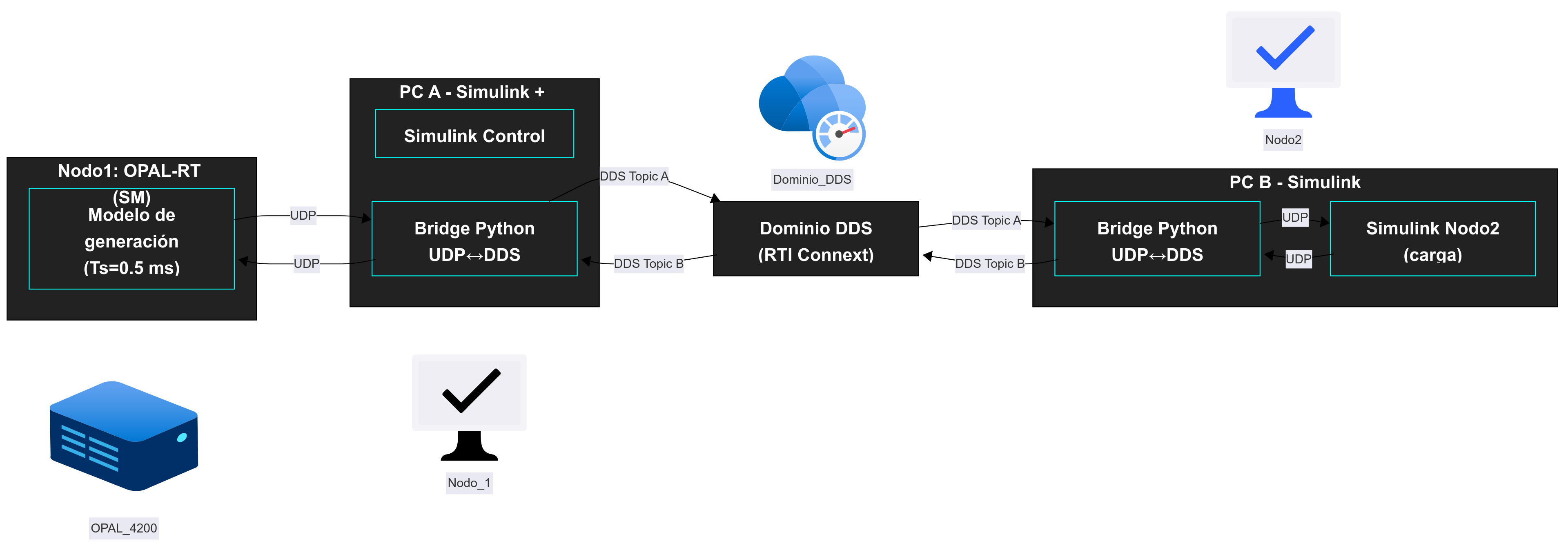
The proposed co-simulation framework is structured into two primary nodes, entirely decoupled and interconnected by Connext:
Node 1 (Master & Control): Integrates the Master Subsystem (MS) responsible for power generation and the Control System (CS). It calculates and publishes the system's state variables.
Node 2 (Electrical Load): Models the consumption device (e.g., an R-L-C network). It is excited by the Thévenin equivalent voltage source (V_MS) received from Node 1 and dynamically returns the demand current (I_demand) back to the co-simulation loop.
To ensure deterministic, real-time interaction, communication is governed by a strict signal contract divided into two distinct flows: Flow 1 (Node 1 --> DDS) and Flow 2 (Node 2 --> Node 1). Both flows use DDS to communicate between them.
This architecture leverages Quality of Service (QoS) policies of Connext to optimize data delivery for HIL testing. The communication layer is explicitly configured to prioritize the most recent data sample and completely eliminate message queuing. This ensures that the simulation loops never suffer from stale data or artificial delays, maintaining strict temporal alignment between the physical hardware and the digital models.
In summary, this work successfully demonstrates the feasibility, scalability, and good performance of a distributed real-time co-simulation architecture built on Connext and OPAL-RT. By establishing rigorous experimental guidelines, this research quantifies the direct impacts of network latency and sampling granularity on both temporal and electrical metrics. Ultimately, it offers a highly replicable, industrial-grade foundation for future studies in smart grid integration and distributed power systems.
code
Kubernetes (K8s) provides a de-facto standard for container orchestration that can manage and scale distributed applications in the cloud. OMG’s Data Distribution Service (DDS), a standardized real-time, data-centric and peerto-peer publish/subscribe middleware, is being used in thousands of critical systems around the world. However, the feasibility of running DDS applications within K8s for latency-sensitive edge computing, and specifically the performance overhead of K8s’ network virtualization on DDS applications is not yet well-understood.
This project research the feasibility of running DDS applications on Kubernetes clusters under various use cases and deployment scenarios. We also evaluate the performance overhead of multiple popular container network interface(CNI) plugins installed on cloud/edge-based Kubernetes clusters.

Currently, we have been working with SDN OpenDaylight instances that control different autonomous systems. We have managed to synchronize them by replicating each network's data to the other controller. In this way, both instances are able to provide backup functionalities between them which is an important characteristic in order to improve the network response time in cases of emergency in 5G Networks.
We deploy two types of controllers which use the DDS to exchange network information as shown in the figure.
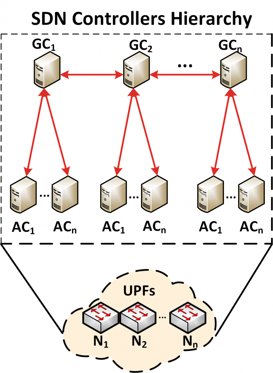
The Global Controllers (GCs) communicate with each other to keep a consistent network state and establish inter-domain flow routes. In the same way, the Area Controllers (ACs) update their GCs when a change in their topology occurs. Similarly, the GCs inform their ACs when there is a change in the global topology that can affect the communication among the nodes under the control of different ACs. Furthermore, the use of the DDS allows a stronger performance during the recovery stages because the GCs share their network information with each other. Thus, if any problem arises with a GC operation, its functions are assumed by another GC.
The testbed architecture is composed of two GCs, each of which manages two ACs. The GCs are physically distributed in Granada (University of Granada, UGR) and Barcelona (Universitat Politècnica de Catalunya, UPC). Similarly, their ACs are placed in these locations, and they can only communicate with their GCs. Thus, we have two SDN domains. The blue dashed line represents the DDS connections over RedIRIS as shown in the following picture.
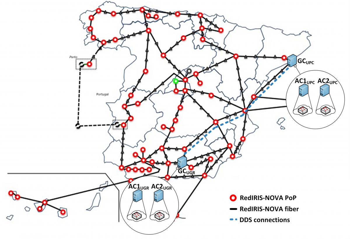
The GCs were configured to support communication over Wide Area Network (WAN). In this way, the GCs can exchange network information and discover other GCs through DDS. The ACs were also configured to support communication over WAN in case their GCs are geographically distant in another SDN domain. However, the first principle was to use private LAN to communicate with controllers in the same SDN domain.
The Orbital Robotic Interaction, On-orbit servicing, and Navigation (ORION) laboratory at Florida Institute of Technology enables experimental research in controlling and operating teleoperated and autonomous ground, air, and space robots. The ORION Lab was designed, developed, and integrated by Dr. Markus Wilde in the period 2014 – 2018. The lab is built around a maneuver simulator and a motion tracking system. It also contains a control room, a supporting electronics workshop, and office space for graduate students and visiting researchers.

The ORION maneuver simulator is located in a dedicated testbed space with a usable volume of 9.6 m × 9.4 m × 3 m. ORION integrates an acrylic flat-floor into a planar, cartesian Maneuver Kinematics Simulator with a workspace of 5.5 m × 3.5 m. The primary component of the Maneuver Kinematics Simulator is a horizontal two degrees-of-freedom (DOF) motion table capable of positioning a payload of 80 kg at a maximum speed of 0.25 m/s and a maximum acceleration of 1 m/s2 along both linear axes.
The motion table is designed to carry a wide range of equipment, such as small industrial manipulators or pan-tilt mechanisms. The ORION pan-tilt mechanisms are custom designed to carry a test article with mass 20 kg and dimensions 0.5 m × 0.5 m × 0.5 m. The motion envelope is ±90° in elevation and infinite rotation in azimuth, with maximum rotation rate 60°/s and maximum acceleration 60°/s2 about each axis. The test article is supplied with power and Ethernet connections via a slip-ring around the azimuth axis.
The ORION Maneuver Kinematics Simulator currently employs two pan-tilt mechanisms. The stationary pan-tilt head is typically used to generate the attitude motion of a target spacecraft model. The target model has geometrical and surface features typically found on a satellite, such as e.g. a parabolic antenna, spherical propellant tanks, thruster nozzles, solar arrays, etc. The moving pan-tilt head is designed to carry a spacecraft robotics test vehicle equipped with a number of robotic manipulators, a capture tool, multiple cameras and distance sensors. In past experiments, the pan-tilt head has also been used to position the base of continuum robots to study capture dynamics. Teleoperation and human-in-the-loop experiments commonly use the two vehicle models mounted on the Maneuver Kinematics Simulator, for maximum positioning accuracy and repeatability.


The motion of the resulting 6 DOF system is controlled by a combination of custom simulation software for orbital relative motion of spacecraft and a real-time soft-motion controller running on a National Instrument CompactRIO system. The motion controller then drives stepper motors in microstepping mode. This enables high precision and constant knowledge of the position and orientation of the spacecraft models. Both open-loop and closed-loop control modes are available, with the position and orientation of the Maneuver Kinematics Simulator components being tracked by the external motion tracking system.
The base frame of the Maneuver Kinematics Simulator forms the bounds of the Integrated Flat-Floor Motion Dynamics Testbed. The 5.94 m × 3.60 m flat-floor is covered with acrylic plates and provides a flat and level surface on which air-bearing vehicles can glide on thin layers of pressurized air to eliminate friction. This enables the simulation of orbital maneuver dynamics and contact dynamics. Every point on the flat-floor is accessible by sensors, capture mechanisms, or robotic manipulators mounted on the Maneuver Kinematics Simulator. This enables the combined use of the integrated kinematics and dynamics simulators in experiments. For testing of capture mechanisms and validation of contact dynamics prediction models, the mechanisms and their control electronics are typically mounted on the Maneuver Kinematics Simulator, the target objects will be floating on the integrated flat-floor.

The High-Precision Air-Bearing Table is located next to the Integrated Maneuver Kinematics and Dynamics Simulator. It is based on a 4.57 m × 1.83 m vibration isolated optical bench covered with a 3.66 m × 1.80 m tempered glass plate. The air-bearing table has superior flatness and levelness compared to the integrated flat-floor. The table is used with air-bearing vehicles to test control systems for satellite formation flight and attitude control and to validate multi-body dynamics models. Multiple air-bearing vehicles are available for experiments, e.g. the pair shown in Figure 4. One of the pair is equipped as “chaser” vehicle with relative navigation sensors and a grasping mechanism. The other is the “target” vehicle equipped with a grasping feature representing a segment of a rocket payload adapter ring. All air-bearing vehicles are self-contained units with their own gas tanks, batteries, on-board computers, control electronics, and communicate with the other elements of the ORION Lab via WiFi.


For experimentation involving air and ground robots, the lab currently uses a commercial-off-the-shelf DJI Matrice 100 UAV and the Pantherbot. The AR Drone enables testing and evaluation of teleoperation and autonomous control modes for uninhabited aerial vehicles. The Pantherbot is based on a MobileRobots PowerBot Autonomous Ground Vehicle equipped with an Amtec 6 DOF manipulator. Pantherbot thus enables ground navigation and robotic manipulation experiments.

All objects within the ORION Lab can be tracked by a twelve camera OptiTrack Prime 17W object tracking system. The cameras are installed along the walls of the testbed space at a height of 2.5 m. The OptiTrack system works by measuring the position of individual infrared reflectors within its workspace. In the OptiTrack Motive software, multiple markers can be combined to represent one rigid body. Thus the system is capable of tracking the position and orientation of a virtually unlimited number of rigid bodies with sub-millimeter and sub-degree resolution. The tracking data is recorded and used for the analysis of experiments involving the motion table, air-bearing vehicles, UAVs, and ground robots. The data is also streamed over a local WiFi network in order to close the control loop for floating and flying vehicles without having to equip them with position and orientation sensors. The common limitations of onboard sensors can then be reproduced by introducing noise or controlled errors into the OptiTrack data. For computationally intensive control algorithms overwhelming typical onboard computers of small UAVs or small robotic vehicles, the control loop can also be closed on a laboratory workstation and the resulting commands be streamed to the vehicles. This introduces transmission delays, but these are typically below 30 ms within the local ORION network.
The ORION simulator uses commercial-off-the-shelf components to generate a light source sufficiently bright to exceed the dynamic range of common optical sensors while providing a narrow beam angle. The walls, floor, and ceiling of the testbed are painted a low-reflectivity black and all windows are covered with black-out blinds to fully control the lighting conditions and to reproduce orbital conditions. The selected light source is a Litepanels Hilio D12 LED panel. The panel generates light with a color temperature of 5,600 K (daylight balanced) with 350 W of power. The intensity is equivalent to a 2,000 W incandescent lamp. The intensity can be continuously dimmed from 100% to 0%, and the beam angle can be varied between 10° and 60° using lens inserts. Therefore, the light can be used to simulate solar illumination and also the weaker and diffuse Earth albedo. The LED panel is mounted on a wheeled tripod for quick positioning anywhere within the lab space.
The control room contains the simulator control workstation, control computers, and an operator workstation for teleoperation experiments. This workstation features a multi-monitor setup for immersive display of video streams, virtual reality representations, and system status data. A number of input devices including joysticks, 3dConnexions Space Navigators, and Novint Falcons are available.

The ORION lab is fully networked. All control signals and telemetry within the lab are transmitted using a combination of point-to-point UDP streaming and RTI Data Distribution System channels. This enables experiments in the lab to be controlled from remote sites.
At the University of Vigo's telecommunications engineering school, students learn the mathematical and physical principles that are necessary to understand telecommunication systems. We also teach them different programming languages, design tools, or in general, how to use computer based and electronic tools to build these communication systems.
In the final year of undergraduate studies, in the subject "Embedded Systems Design", we ask students to design and build a small autonomous vehicle (a quadcopter or a robocar). To do this, they must first create an "autopilot" to manage the information from the sensors, distribute it to the various information processing and decision making systems and finally apply the control commands.
The students build a distributed system in which they use RTI Connext DDS to exchange information between the different blocks of software.


Research studies focussing on the integration of COTS sensing technologies with UK MoD standards compliant vehiclular architectures and data management processes for crew workload control. Providing interoperability between complex situational awareness systems of systems for future crew station development, utilising RTI DDS coupled with Interoperable Open Architectures (IOA) approaches.

![]()
NtoM is a concept of operations which pursues the feasibility, from a human factors perspective, of having a single pilot/aircrew controlling several remotely piloted aircraft systems (RPAS) at once in non-segregated airspace. To meet such feasibility, this multitasking must be safe and not interfere with the job of the air traffic controllers due to delays or errors associated with parallel piloting. To that end, a set of measures at several levels are suggested. A prototype of the system orchestrating the enviroment described by the ConOps was implemented to illustrate the potential of the concept. The connectivity between the clients for pilots and controllers and the server was done using RTI Connext DDS, which is particularly interesting in the case of the RPAS to simulate different scenarios of Quality of Service of the link. | 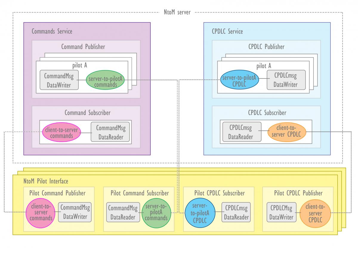 |
The Health Aggregator Manager (HAM) project, developed by the Center for Strategic Health Technologies (NUTES), from Paraiba State University (UEPB), Campina Grande, Brazil, in partnership with Signove Technology S/A and LIFEMED Medical Devices, aims to create a high-level system that serves as a managing interface of medical measurements, taken by devices that comply with the ISO/IEEE 11073 standard, using the Antidote, which is a set of free libraries that implement the standard. The contribution is to present a reference architecture and implementation for an open cyber-physical system, with sound documentation and practices. The HAM was developed using agile practices and a requirements-based engineering approach. This mixed approach satisfy safety requirements defined by this type of health/medical system and enables the demonstration of compliance with main software standards.
 and Health Aggregator Managers (HAM)")
![]()
![]()
The DRONEXT project addresses the design of a multi-service communication framework for the protection, safety and defense applications of the secure societies of the future. Our solution uses an infrastructure of Micro Air Vehicles (MAV) to provide communications and service coverage in delimited geographical areas, in which there is no appropriate communications for the applications to be deployed (non-existent or unavailable due to a natural disaster for instance). Additionally, the framework under development uses larger tactical Remotely Piloted Aircraft Systems (RPAS) to communicate distant geographical areas, where MAVs coverage is supported, with a Ground Control Station (GCS), which provides connectivity towards control centers responsible for coordinating the execution of the operations that required the network deployment.

Our framework makes use of virtualization techniques, to support the fast and adaptable deployment and upgrade of any functions and services over the MAV infrastructure (e.g. VoIP services, routing, positioning algorithms, video recording and transmission, etc.). The use of virtualization, and the coordination of MAVs and larger tactical RPAS, provides the flexibility to address a wide variety of use cases related to protection, security and defense. An overview of the framework design, along with a subset of its use cases, is presented in Figure 1.
As connected autonomous vehicles are becoming a reality, it becomes paramount to introduce the fundamentals and the design concepts of such systems into engineering curriculum. From a different perspective such systems offer an exciting platform for enhancing student motivation and sense of mastery. During the spring semester of 2015, the intelligent automation systems graduate course at the department of Industrial Engineering and Management, Ben-Gurion University focused on autonomous mobile robot systems, with a specific emphasis on IOT connected autonomous vehicles. To facilitate student understanding of the theoretical and practical foundations along with the complexities of such systems the curriculum was designed around a collective bottom up construction of an autonomous driving system based on a team of EV3 Lego robots and a 3m squared road map (Fig 1). The course was divided into two sections: autonomous mobile robots and connected autonomous vehicles. As part of the course requirements, the students, divided into teams, constructed two mini projects implementing the theoretical concepts studied within each section. For the first project the teams were required to build a mobile robot capable of staying on the road and driving between junctions according to the shortest route (calculated offline). The robot was additionally required to stop before each junction and in case of identifying an obstacle (e.g., a car in front of the robot) not to get closer than a given distance from it.The theoretical concepts studied included robot design, path planning, and motion control (Fig. 2). For the second project the robot was additionally required to communicate with a central traffic control system before and during crossing of each junction. The theoretical concepts studied included team control, communication, and software design. RTI DDS was used for illustrating data-centered system design and programming and for communication quality-of-service design. One team additionally implemented an online visualization of traffic congestion using Excel DDS add-on. The ease of constructing applications using Lego EV3 and RTI Connext, along with adherence to a simplified environment (planar surface, right-angle turns, and color-based information) enabled hands-on appreciation of both low and high-level concepts including design, control, communication, and collaboration issues. During the final exam the students successfully discussed system safety features and ethical considerations and designed a data centered implementation of an IOT application for connected vehicles, e.g., using the autonomous car as a delivery option for online purchased goods, or an online pizza purchase to-go App (Fig 3).
More details about the Integrated Manufacturing Lab in which the course took place can be found in:http://in.bgu.ac.il/en/engn/iem/IMT/Pages/default.aspx
![]()
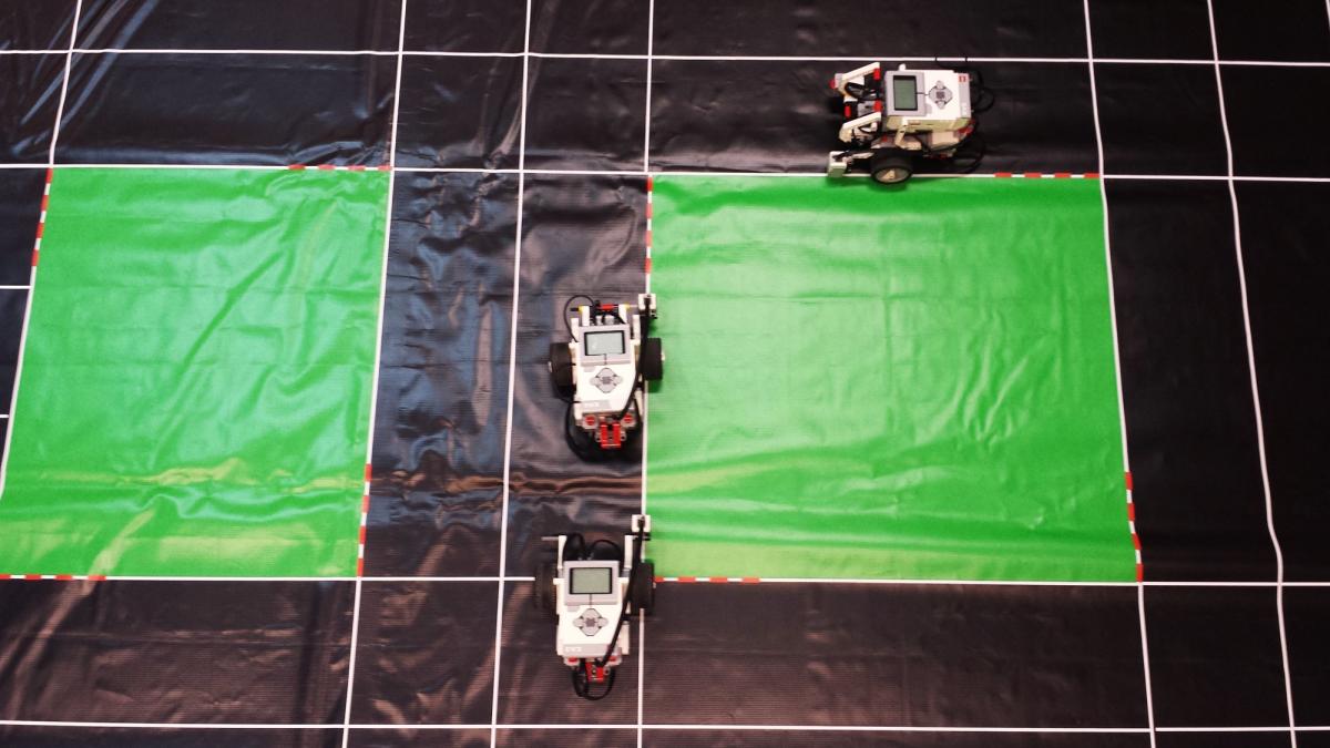
Figure 1: Three EV3 Lego robots on the road map
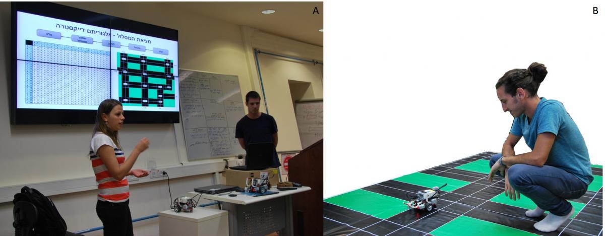
Figure 2- A: Two students presenting their path planning algorithm. B: A student closely monitoring his robot during project presentation
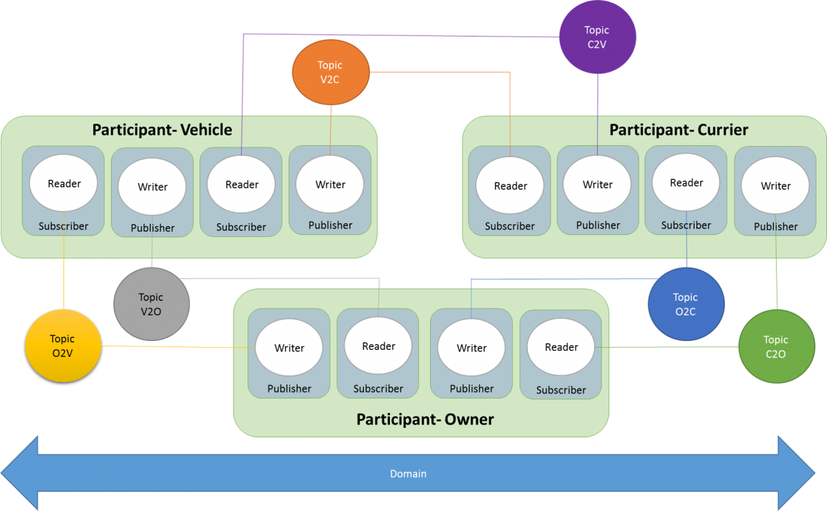
Figure 3: Suggested design for using the customer’s autonomous vehicle as a currier by the delivery company